
WebMaka

39777

47

2

Let's start at the end as per Imgur tradition, with finished product versus design!
This is a small but powerful smart power switch for smart projects. It can switch up to 6A, communicates with smart loads (where "smart" basically means "there's a single-board computer or microcontroller somewhere within the project") or can act as a basic power switch for dumb loads, sends and/or receives shutdown requests, detects laggy or crashed smart loads and reacts to lag (with a status LED flash pattern) or crashes (by shutting the load's power off), detects and warns if there's a boot failure, and even handles power failures if used in a project that has some form of power backup. It only needs three addressable I/O pins on the load, and does not require the use of SPI or I2C so those are unimpeded for other uses. (The only catch is that its microcontroller uses 3.3-volt logic and is not 5V tolerant, so using it with 5-volt logic will require logic level conversion.)

It started with a need, and led to a design.
I needed a "smart" power switch for a few "smart" (again, read: there's a Raspberry Pi or Arduino or something along those lines involved) projects, and while these do already exist, I wasn't impressed with the features I was seeing, and most of them are platform-specific, which might pose a problem if it's designed for use with, say, only Raspberry Pis and I'm using an Arduino in a project.
What I wanted was a pushbutton-toggled load switch that could work with "dumb" projects as well as "smart," and had useful features when used with "smart." And I wanted it to be hardware-agnostic so I can use it for/with anything I build that uses a 5-volt power supply.
Necessity being the mother of invention and all that, I broke out KiCAD and got to it.
I designed a jumper to set it into either basic mode (for dumb" projects - it merely acts as a power switch with no special fancy crap) or advanced mode (for "smart" projects - this enables power failure detection, lag/crash detection, boot failure detection, and bidirectional shutdown signaling so either the switch or the thing it's connected to could trigger a shutdown). The design uses a load switch rated for 6A @ 5.5VDC max, which is more than ideal for most of the Single-Board Computers out there.
I added another jumper to control automatic start/restart as well, so projects that need maximum uptime can be auto-started on power-up and auto-restarted if the SBC stops or dies for any reason.

A little Gerber exporting, some Excellon drill file exports as well, some time on a website, and a five-day wait later, a stack of leeeeetle circuit boards arrived. (The coin is a US quarter.)
I'm calling it "b(you)ttOn," as is evident by the logo on the back. It's pronounced bee-you-tahn, which is my favorite way to intentionally mispronounce "button." The "you" part is who it's for - those "yous" out there that share my love of building things, and ending with the "on" part of "on/off" is basically what it does, turn things on. (And also off. But that doesn't translate into a one-word term as readily.)

Solder paste + stencil = win.
And that is not a credit card. It even says as much.
I'm using all RoHS-compatible everything, including lead-free solder paste, so it's as environmentally friendly as electronics can be right now.

First round of making things out of parts is to bake the surface-mount parts and solder paste. Second part involves a soldering iron for the through-hole stuff.
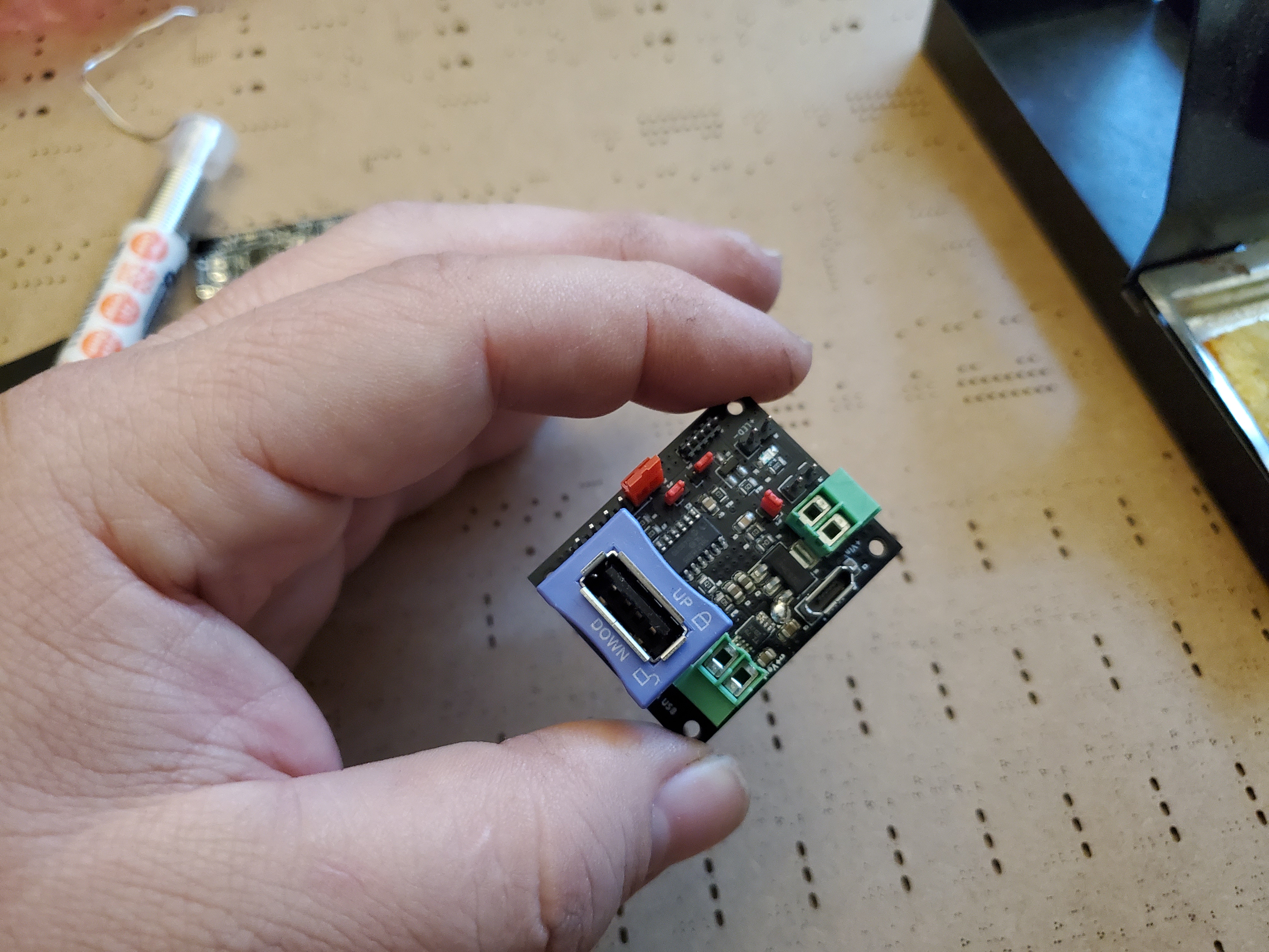
A completed prototype! It's pretty small - 1.25 x 1.55 inches for freedom unit users, and 31.75 x 39.4mm for the rest of Earth.
Also, LOCKING USB port.
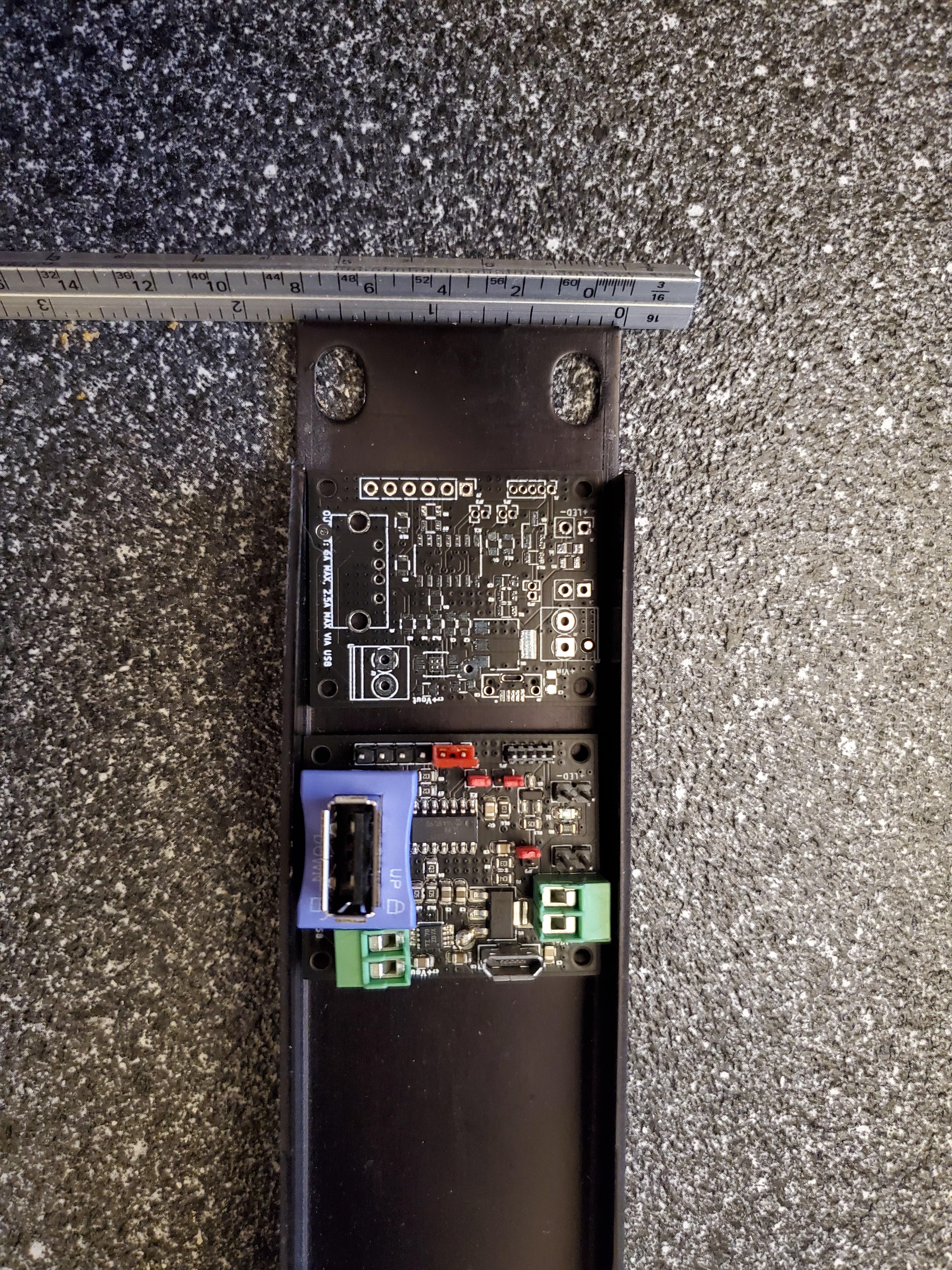
If the physical dimensions seem oddly specific, there's a reason for it: it's designed to fit easily into a 1U rack enclosure. Folks building 5-volt projects for rackmount applications will probably find this little detail useful.

After writing and pushing firmware to it, I applied power. Nothing happened, which was what it should do at the start.
Then I pressed the button (a bog-standard mobo reset switch) connected to it via that blue/white wire pair. It then stopped doing nothing and started to instead do something. That something involves turning on a 6A load switch. Whatever is plugged into that big USB port gets powered or not-powered with the touch of said button.
This is the startup pattern for its status LED. If a SBC (Single-Board Computer, in case anyone missed the several times I translated this abbreviation) like a Raspberry Pi were connected to that big USB connector it'd be getting power and booting. Both the USB 2.0 port and the green screw terminals to its upper-left in the picture are powered at the same time, so one can route to a SBC and the other to power additional circuitry so that part of the load can be moved off the SBC's internal power system. (Or, backpower the SBC through its GPIO port if it supports GPIO backpowering.)

And this is the status LED pattern it shows when a connected SBC is up and running. It gives the SBC about five minutes to boot, and if it doesn't, it'll flash a simple on/off warning and turn the SBC off.

It has one thing I haven't seen in any other device of this type: lag/crash detection. If it sees the connected SBC is lagging, it changes from the slow sinusoidal pulsations to this pattern, a sharp heartbeat. Once the lag goes back to normal, it reverts to the "running" animation.
If the SBC just plain hangs or goes away, it flashes a simple blinking pattern and shuts off the crashed SBC.

The shutdown process. It tells the SBC to shut down, a script running on said SBC reacts accordingly, and once it detects the SBC has shut down it turns itself off.

Of course something like this will require some software on the other end if there's going to be any sort of communicating between slot A and tab B, so to that end I whipped up some Python scripting that sends a heartbeat to the power switch board so it knows the load is up and running, as well as handing shutdown requests both from the board to the Raspberry Pi 3 in this case and vice versa. So, I can shut the Pi down safely with a button press or by issuing a "sudo shutdown now" and the board will automatically turn itself and the Pi off once the Pi finishes its shutdown and HALTs. No having to fiddle with power cords, no filesystem corruption from an accidental power cut at the wrong time, etc. This code can run as a cron job (restart-triggered) or be thrown at systemd and run as a system service.
The above is the config script for the script that does the actual work. As of now it's only for Linux distros that use sysfs for GPIO access, but I'll eventually make a libgpiod version for the latest kernels since sysfs is deprecated. It auto-detects the device it's running on and tries to load a pinout description file, first locally and then online, and basically makes setting up the heartbeat/comms script a matter of picking what GPIO pins are being used for what. Using the config script is pretty self-explanatory, as shown, and I currently have pinout files for Raspberry Pi 2/3/4/Zero/ZeroW and Odroid C1/C2, and I'll bake more for other popular SBCs on a as-requested basis. This saves having to know or find the sysfs export codes for each GPIO pin.

If there's enough demand to justify the tooling-up it'll take (and FYI, it takes around fifteen thousand bucks to set up an in-house small-scale PCB production line), I'll do a whole product line. Multiple sizes and voltage ranges of smart switch, UPS boards, expansion boards, whatever makers want/need/wish for.
For example, the above is what happens when I add my smart switch to a supercapacitor UPS and a powerful boost converter. It'll push a full 3A @ 5VDC for 30 seconds (with the runtime stretching out as load decreases), it'll run in standby mode without user intervention for over a decade (something a Li-PO battery based UPS "hat" or "shield" can't do), and basically convert any SBC-based project into something that can automatically shut down safely during a power failure and restart itself when power is restored - perfect for AC-powered high-uptime projects like tiny datalogging servers.
WebMaka
UPDATE: https://www.reddit.com/r/ElectronicsList/comments/ekm7hw/i_made_a_thing_for_switching_power_to_other/
scottsinflavortown
WebMaka
Lierofox
But does this contain a
incorrecthorsestapler
Why would you set up an in-house production line, rather than going to CM?
WebMaka
Because it'd buy a few days before someone steals and mass-produces a clone. Outsourcing has become problematic.
incorrecthorsestapler
With tariffs being what they are currently, US based CM’s are somewhat reasonably priced, might be an option.